
So a while back I was browsing the internet and came upon a project by Jet Propulsion Laboratory to build your own model of the Mars Curiousity rover. It sparked my interest because I had been looking for something to do. I was a little bored.
It didn’t take long to realize how much this would cost and I started looking for an alternative and eventually I an article at Hackaday.io which led me to this repo on github by Roger Cheng outlining a cheaper version called Sawppy. It wasn’t very long before I realized that this was something I could afford over time.
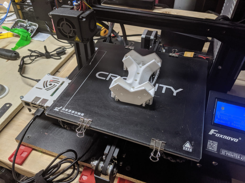
It’s important to note that I don’t have a very advanced workshop. A lot of my tools are cheap knock-offs or budget tools from places like Harbor Freight. I’d even go as far to say that at least a quarter of my tools were given to me or found at a thrift shop. I did, however, have an Ender-3 3D printer that I had just recently modified with a BLTouch for automated calibrated bed-leveling. I was itching to get started.
Like any grown man itching to get started playing with a new toy I began perusing the git, but mostly picking out parts to 3D print (in no particular order). In hindsight I realized I should have actually followed an orderly path to see this creation to its end and my folly had many a consequence.
Among those were not realizing some of the parts needed to be mirror, not testing the tolerance of my print against the joining of the parts (greatest of those headaches was setting the bronze heat inserts), and needlessly printing out some parts at too low a resolution to speed the process which lead to broken parts during construction.
As it were, the journey so far has been instructional and has tested the boundaries of my patience and skill. In many instances I diverged from the path the Roger had set out for me to experiment with my own ideas. Some succeeded, some failed.
I have always been an Engineer at heart. But the foundation of my skills have always been in software or electronics. Actually having to cut and measure and fit together a myriad of parts was pretty new to me and the experience has prepared me, nay, emboldened me try new and more advanced projects.
But lets cut to the chase.
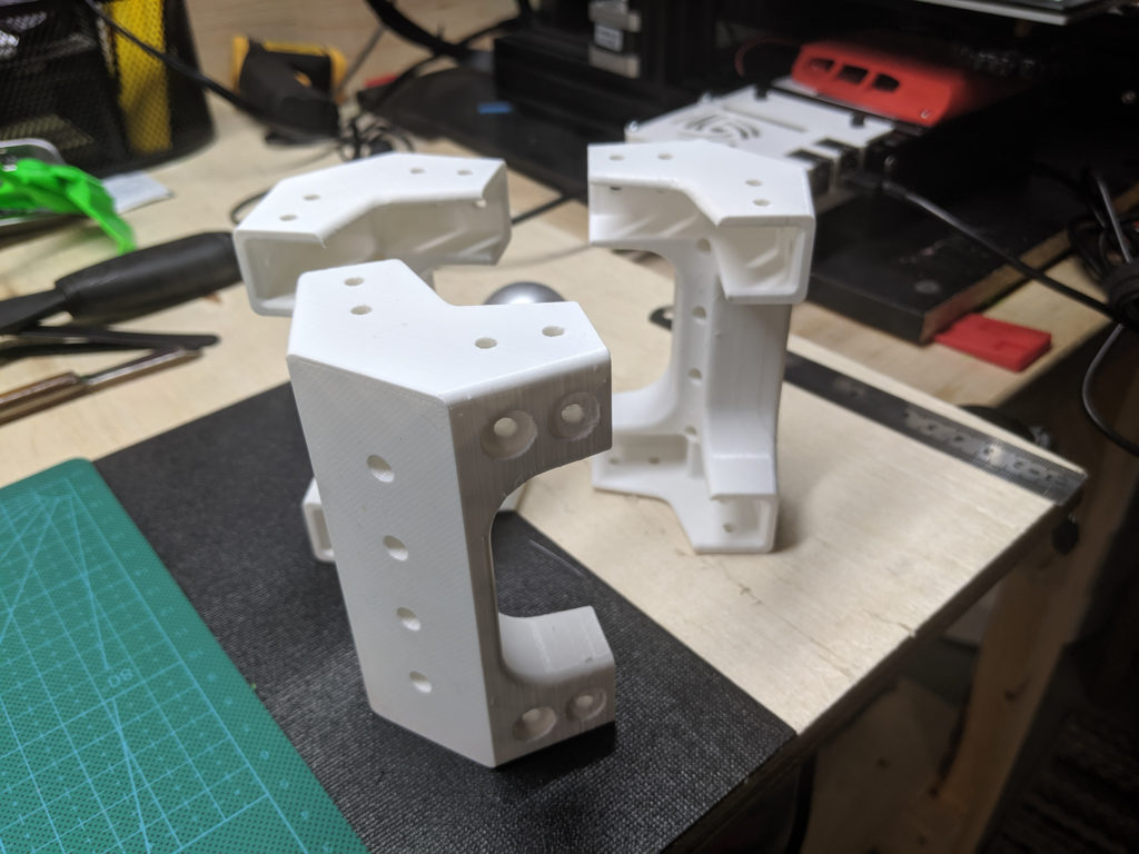
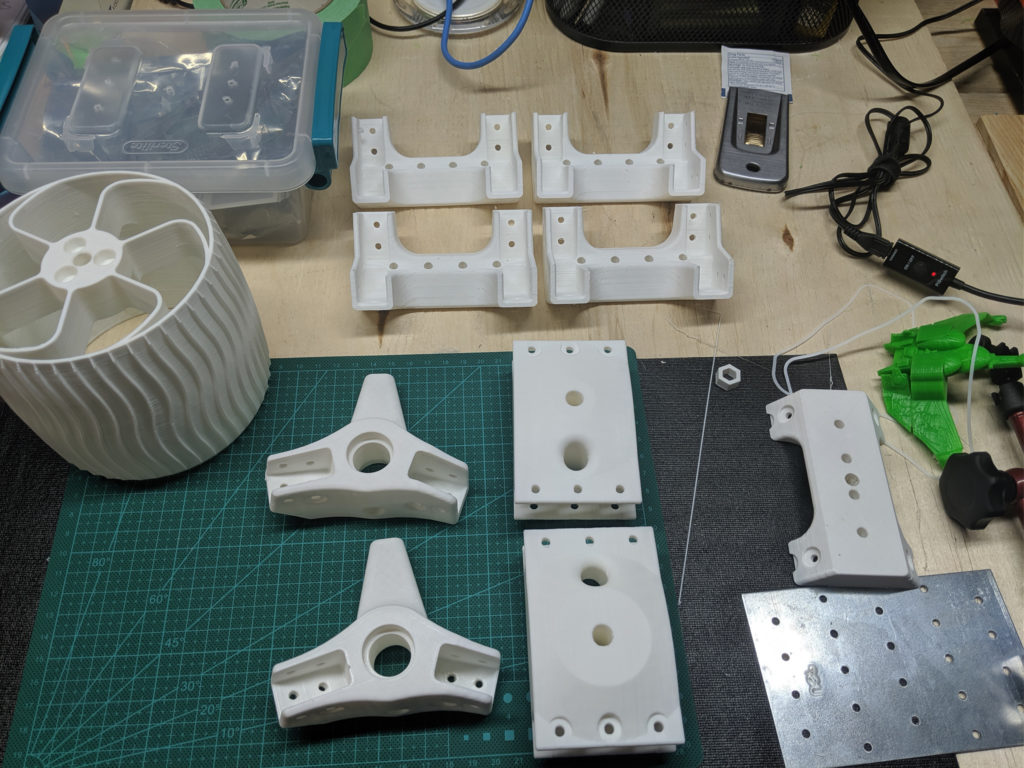
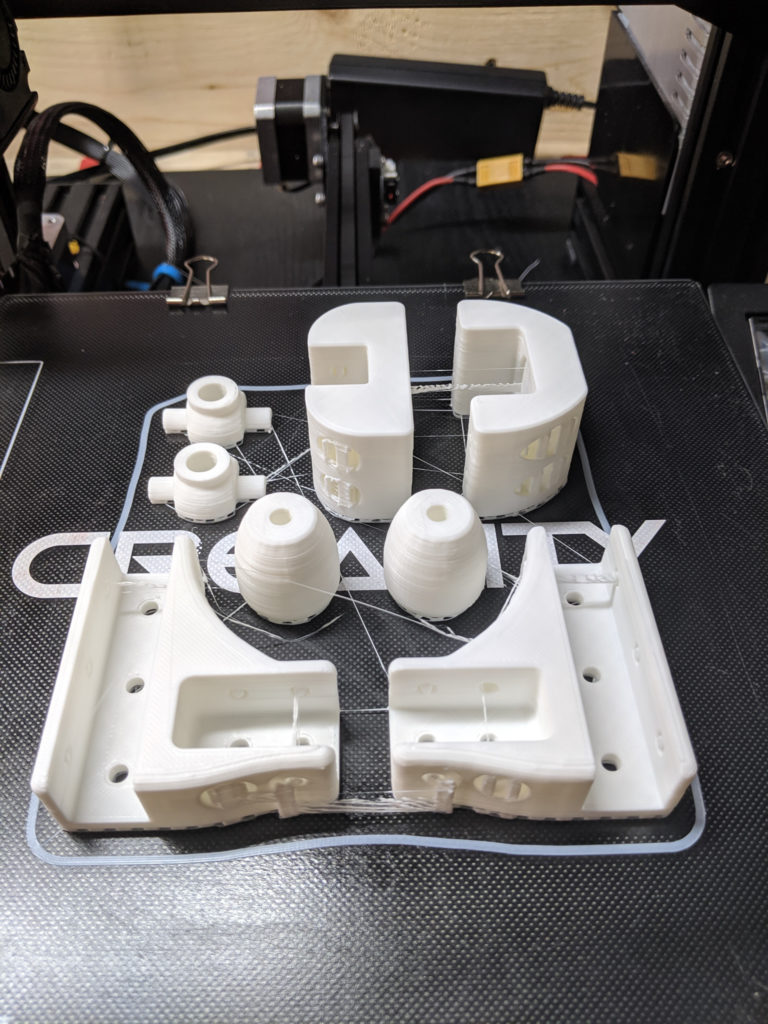
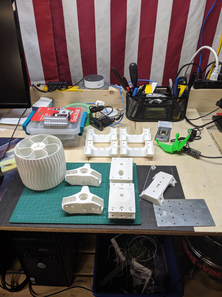
Despite the setbacks brought upon by my eagerness to just jump right into the fray, I feel like I initially made very good progress. I realized the bulk of work was going to come from 3D printing the parts and I began that collection with haste. Starting with the corners of course, because the was the bulk of the body and the shortest route to having something tangible to show for my work. From there the collection grew.
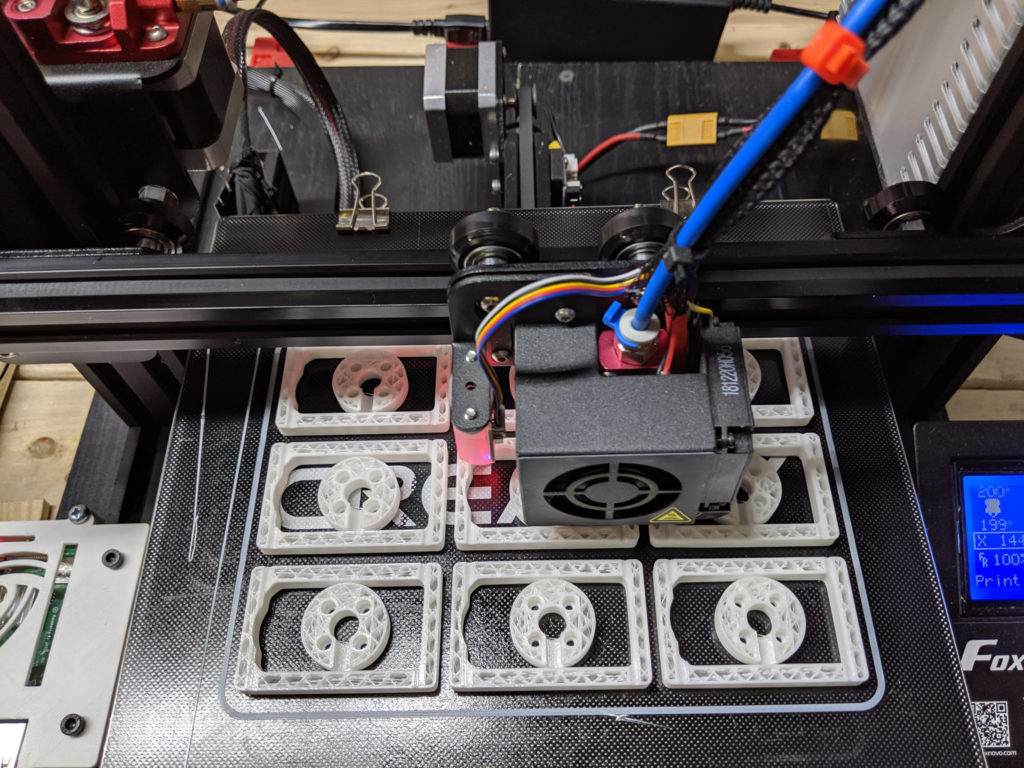
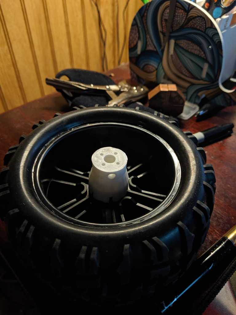
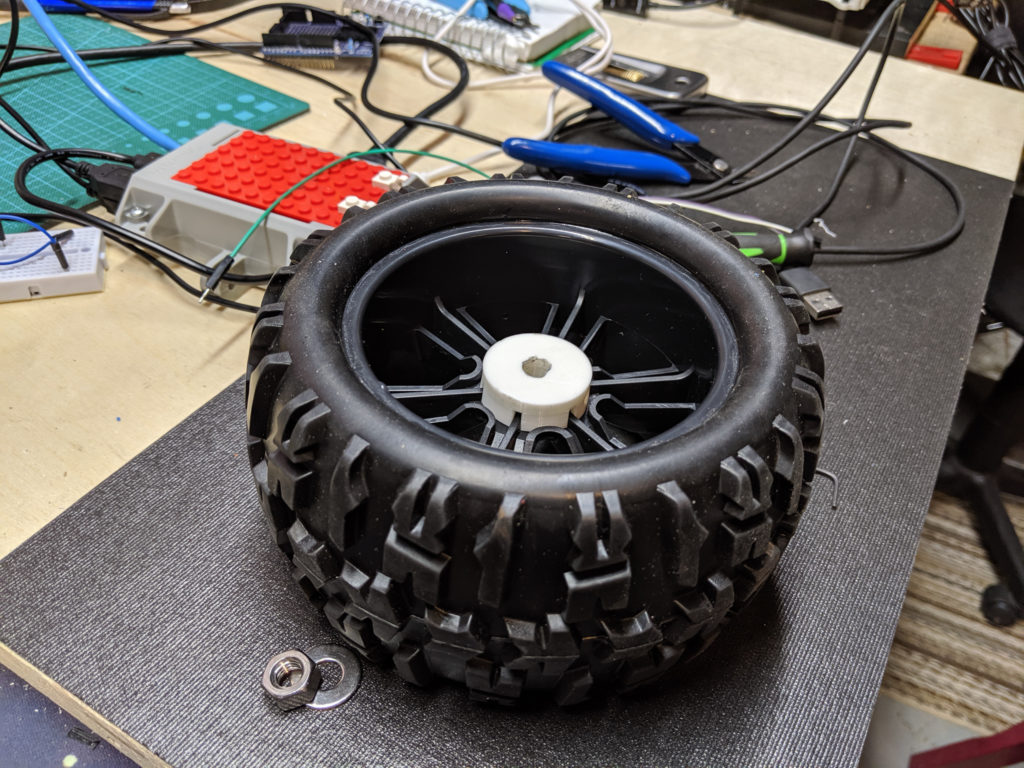
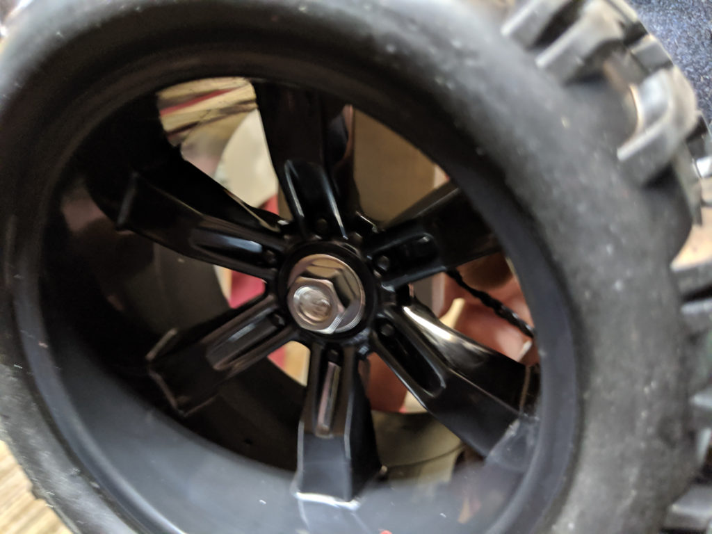
At one point I realized that the wheels were going to be a pain my ass. Not only did they take about 12 hours to print, if they ever broke I had to add another 12 hours just to fix it. So while I did print out one for prosperity I decided to use RC monster truck wheels. Admittedly, this decision was also a pain in my ass because I wanted the wheels to be as close to the original size of 124 mm. Eventually I settled on a style and purchased some 6 inch wheels (150 mm) that were 3.6 inches wide. from China. They took FOREVER to arrive.
Alas this decision required some design modifications to facilitate connecting the wheel to the servos. But I needed the servo’s first before I could even entertain the idea.
I purchased all 10 of the LX-16a servo’s on AliExpress hoping against odds that I would receive operational devices (let alone receive them at all). When they did arrive I was ecstatic. This part of the project was by far the most expensive despite having searched far and wide for the cheapest price. I ended up getting all 10 and the debug board for around $150.
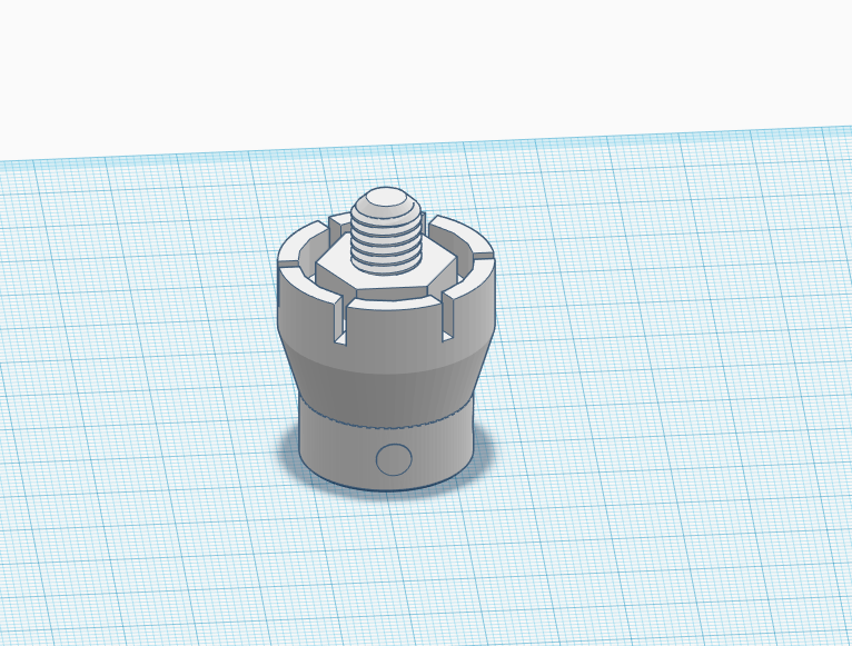
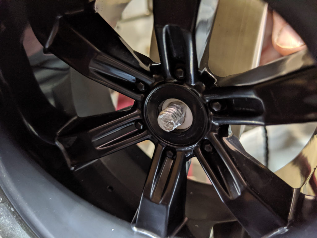
After making sure the servo’s worked (which was preceded by setting up the Raspberry Pi) I set about designing a wheel coupler. After some careful measurements to make sure it would snap onto the inside of the wheel and that the hex nut would fit snugly I printed out some copies to test. Sadly I discovered that the bolt extension of the v1 coupler would crack or snap with too little force so I decided on a pass-through version. Version 2 failed because while I could get enough of the shaft to pass through the hole, I couldn’t get a lock on that rod to keep it from shifting. So version 3 was born with the caveat that I would have to mill a thread onto the shaft. Almost perfection.
With all the parts purchased or made I began to put Sawppy together with a fervor. I cannot tell you how many times I dropped an allen wrench. I mean the number of times I dropped an allen wrench was insane. It happened so much I started coming up with an algorithm to predict when it would happen and at what frequency. I seriously was becoming so annoyed I almost started charting it. The second thing to get dropped the most were the M3 nuts, followed by the M3 bolts. Ironically, my workshop floor is covered in a pure black padded work mat so either the item bounced so incredibly far or was invisible to the naked eye because of its color (noted to self to buy stainless steel next time).
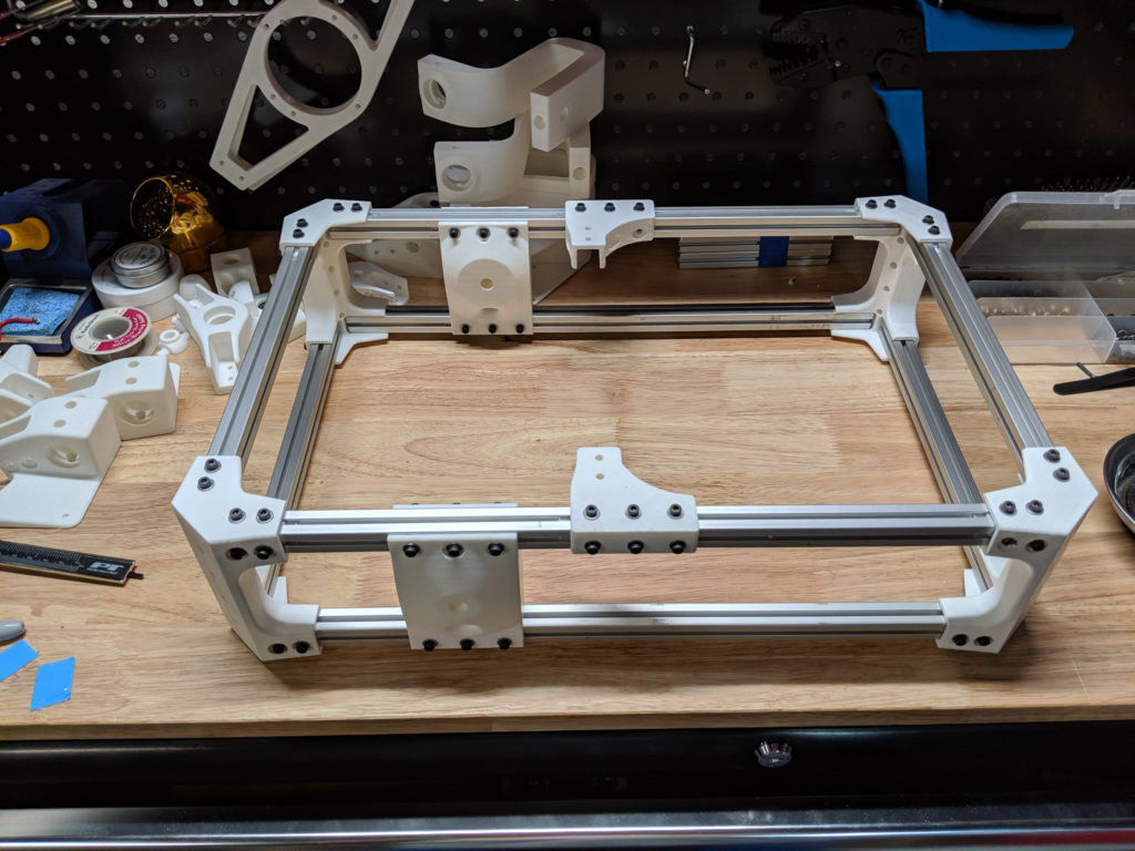
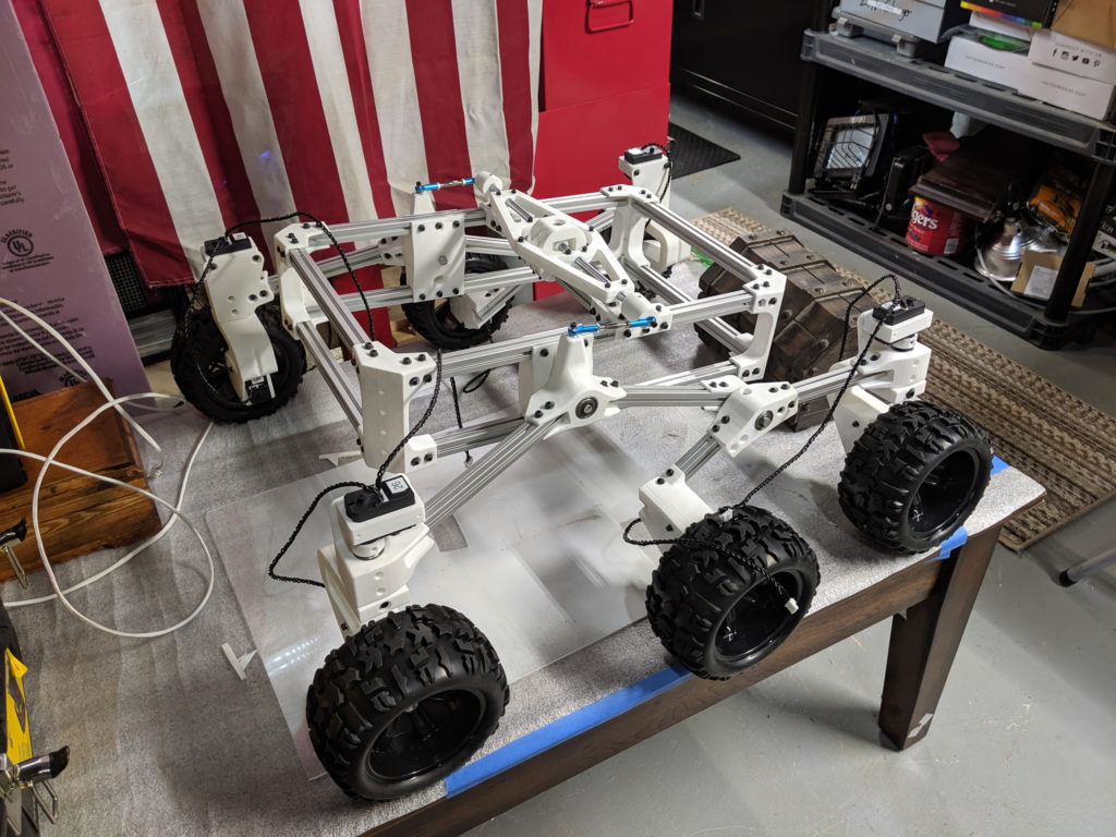
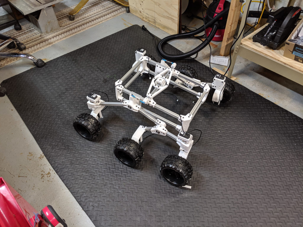
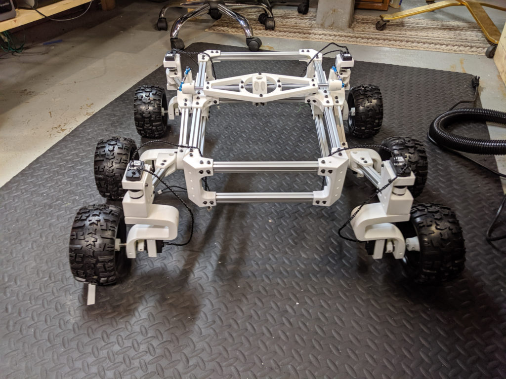
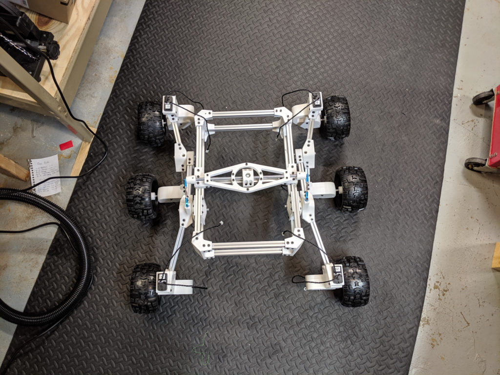
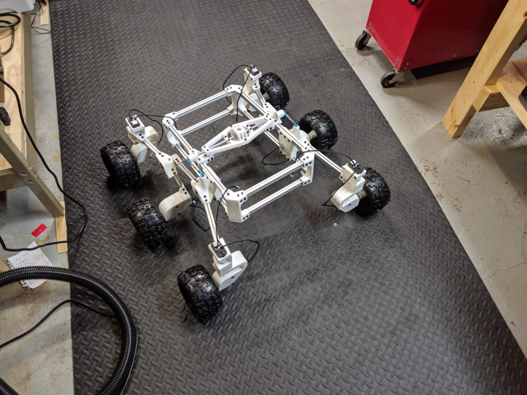
Eventually I had her built.
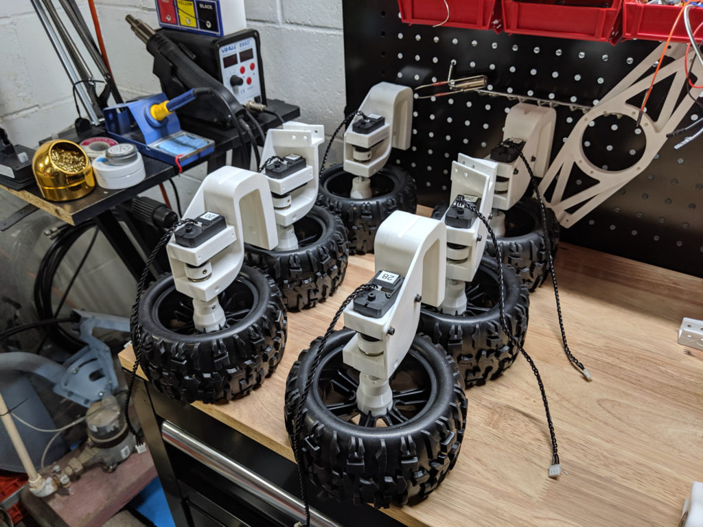
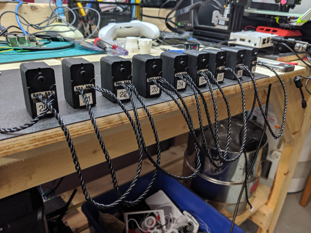
But was I done. Oh no. In order for this baby to run I had to have all of the servo’s trained together. But for the life of me I could not a reliable source for the very specific female connector each of the servo cables used. At this point I contacted Roger Cheng on twitter and he suggested what should have been obvious to me from the start: splicing in-between the existing cables. I’ve always been reluctant to alter perfectly good and existing ‘anything’ and was doubly more reluctant considering how hard it was to locate these connectors, let alone purchasing the cables by themselves would probably require me to buy a servo. So I set to it and before long had a wiring rig that I could dangle over to my RasPi and debugger and I began installing the software required to control the rover.
It’s kind of funny how much attention I put into labeling all my servo’s so that the config matched that of the software and Roger’s instructions. But in all the confusion of fixing this, adjusting that, and taking this or that apart — EVERY ONE of those things ended up in the wrong spot.
*sigh*
I rewrite the configuration with my new layout, measured out the dimensions of each wheel location and went to clone the software and install all the dependencies on the RasPi but for the life of me I couldn’t get Flask to run. Mind you, I am not a *nix noob. But when it comes to installing something someone else wrote without fully understanding the versioning of all the dependencies required it is an understatement to say that error messages are often misleading and at times completely useless.
Turns out I had Python v3 installed on the Raspi so I installed 2.7 and with a little command line alias magic had 2.7 running in its stead. Also, admittedly, cloning gits was always a little confusing to me and this was my first time running Flask. Ever. The instructions to export FLASK_APP=SGVHAK_Rover turned out to work when I did export FLASK_APP=SGVHAK_Rover/__init__.py instead.
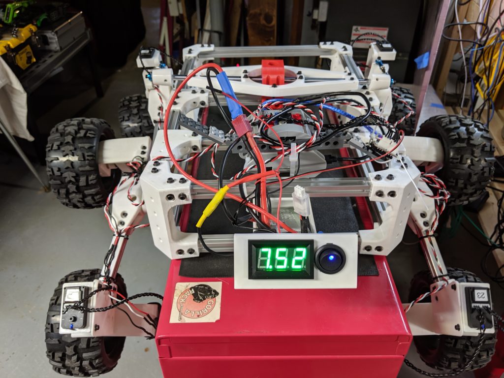
Boom. The server was running and I opened it up and started messing with the UI and it become very, very, apparently clear that something was wrong. First thing I noted to myself is while a 500maH battery might be good for testing one or two servo’s at once. It will only last a few minutes with 10. While I had the mongo 5200mAh battery in the wings for the final touches, I had a few 1500’s in my drawer that worked. Secondly, all the fittings on the servo’s were loose as HELL. There was so much play I feared things were just going to start falling off. I forgot to mention just how much trouble I had had putting those heat inserts into place while I was building this. At first I tried to sink them in from the outside like a complete moron. Sometimes they fit, but more often than not, due to my lack of tolerance testing of the hole diameters when printing, they were too loose to do anybody any good. While I was willing to print out some of the items, there were a few cases when I just opted to use larger diameter inserts such as an M4 or M5. I also read Roger’s instructions better and realized that i should have tried inserting them from the inside. Ultimately, this method would have saved me a lot of trouble but I had another idea in mind.
The problem was even if the insert were snug as a bug, you were still going to suffer some play simply because of vibration. I can’t tell you how many of the M3 bolts on the body were loose just from moving it around. So you can imagine adding spinning and bumping to the mix would make it worse.
In all of the lessons I learned from making Sawppy I feel like the details I am about to share are the most important. After all, the whole idea was to make a rover and the whole concept of a rover is something that roves. This does no good if stuff is constantly coming apart. And while Roger’s solution of using Loctite 243 to prevent this, I felt like ‘gluing’ the parts into place was counter-intuitive and would make for unneeded difficulty in future repair or modifications. So I did this instead.
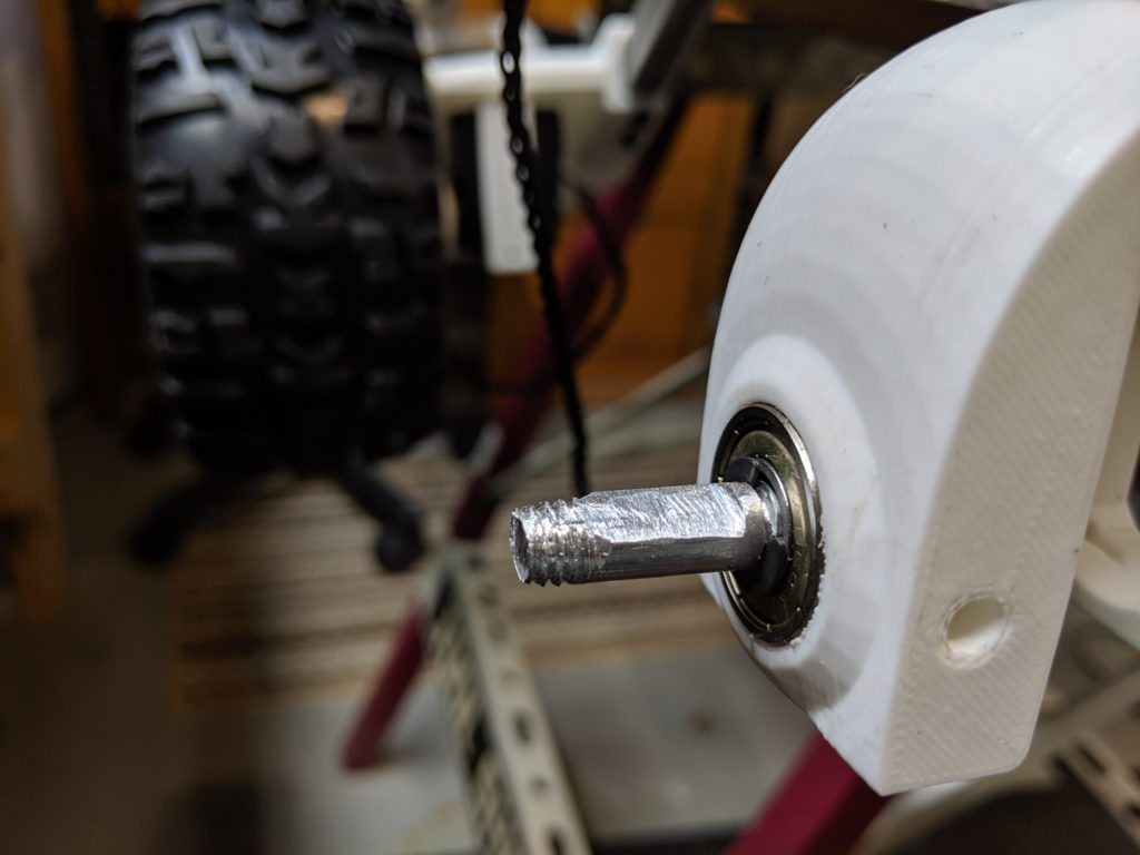
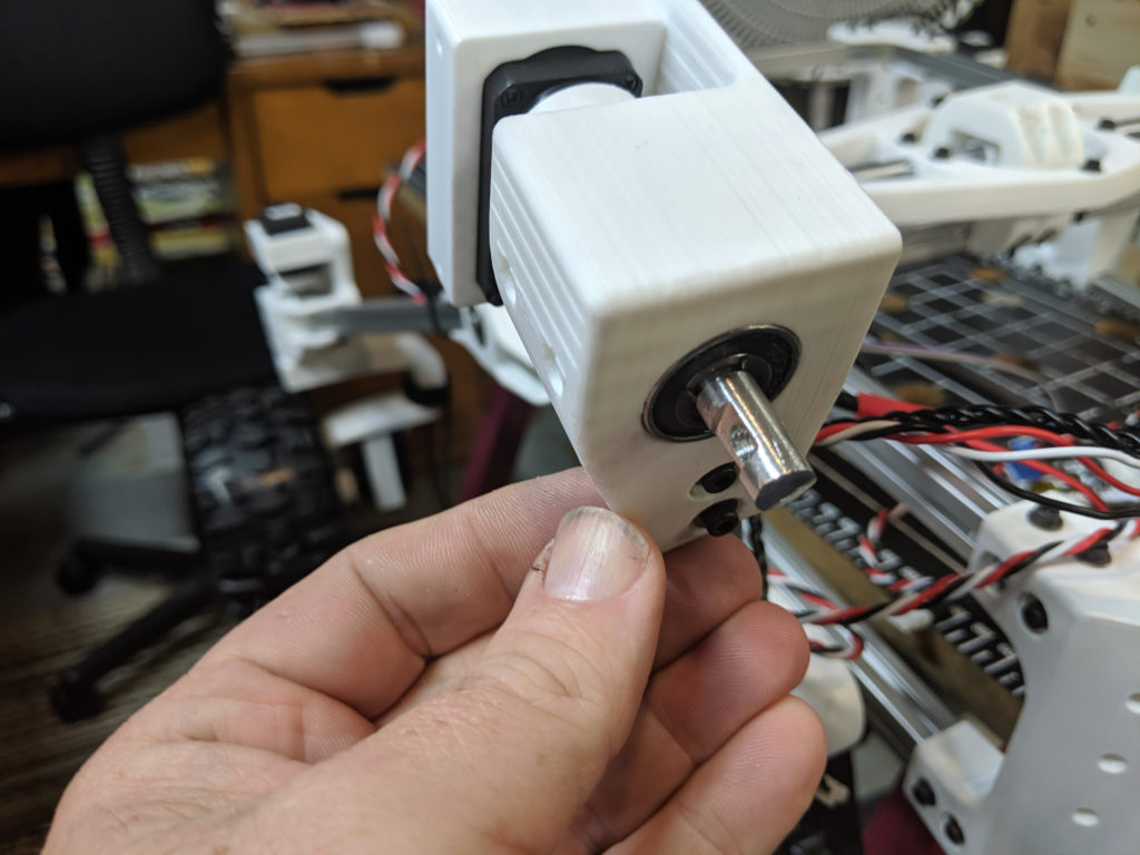
Using the same $16 Metric Tap and Die set from Harbor Freight I used to put threads onto the shafts for the wheels I decided to tap threaded holes for whatever bolts I needed to hold a coupler in place. Mind you this works best if your shafts are aluminum.
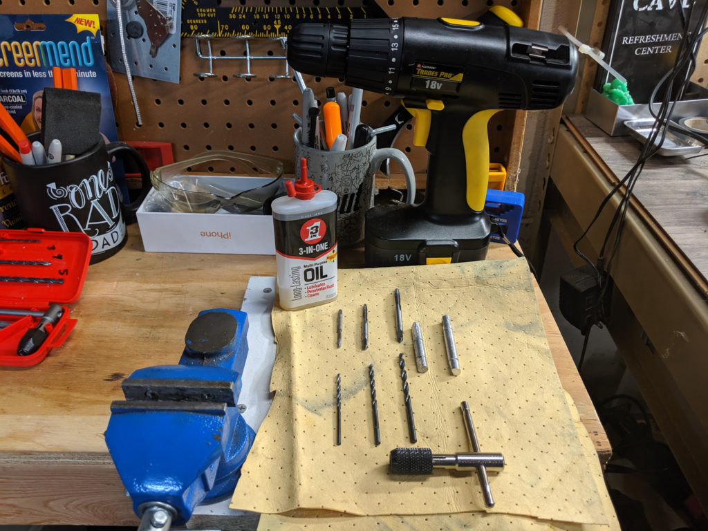
The tools I used were a simple vise, a battery powered hand drill, the tap and die set using SAE drill bits to start the holes. Using 6-32 for M3, 8-32 for M4 and 10-32 for M5 were applicable. To be honest I don’t even know if they make metric drill bits and I had these standard bits lying around.
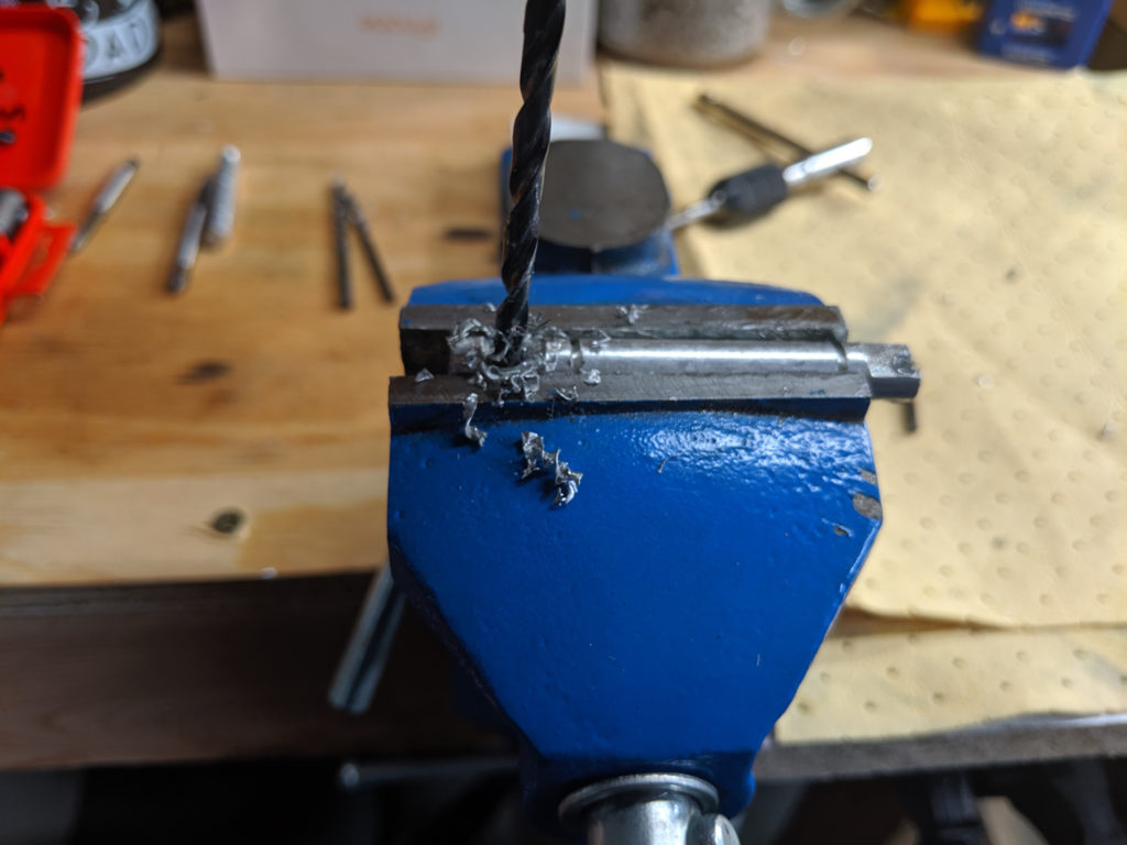
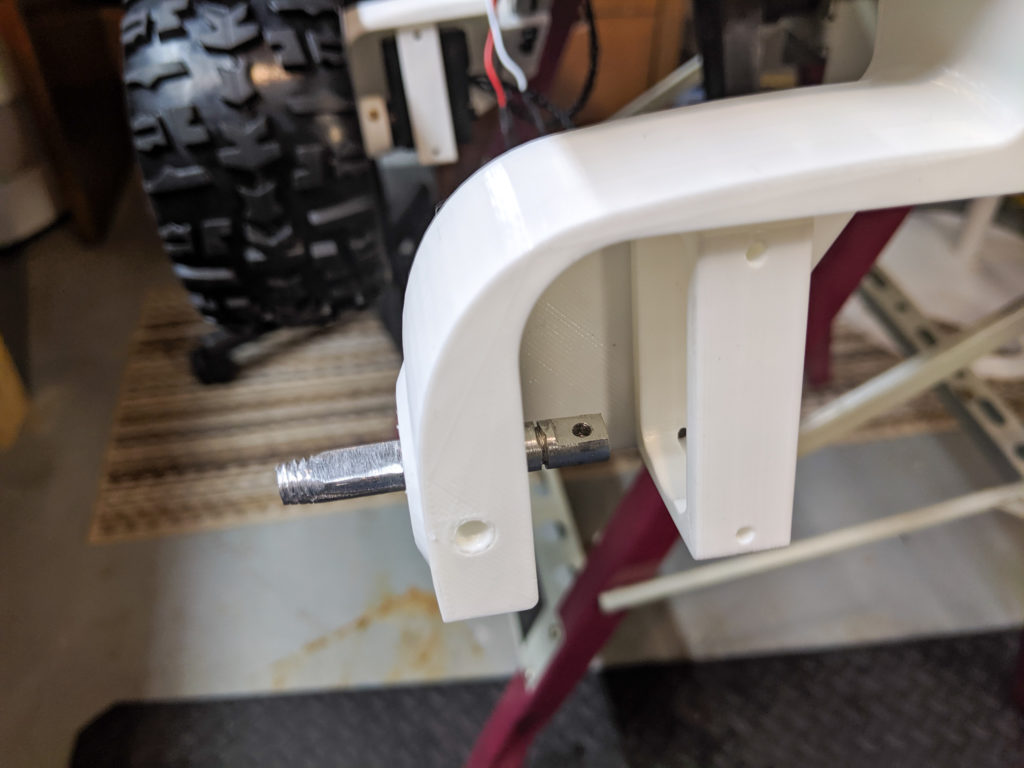
1) Using whatever size bit you needed for the metric hole you wanted to thread, you put the shaft into the vice and drill. Slow at first to make sure you hit your mark, a little faster when you are sure it won’t slip. Make sure you add some oil to help with the cut and prevent over-heating.
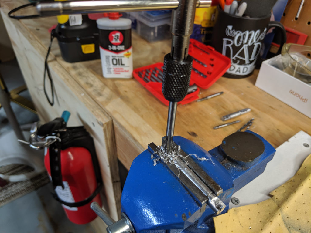
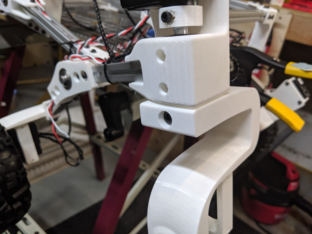
2) Once the hole is drilled, insert your tap. In this instance I am using an M5 tap because I wanted the steering knuckles to be held on by something thick. If you used the right standard drill bit, you will be through in a matter of seconds.
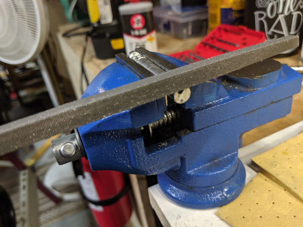
3) Clean up the shavings afterwards and file off any burs. I also take measures with my shafts by taking them over a belt sander to make sure they are smooth and fit better through the bearings.
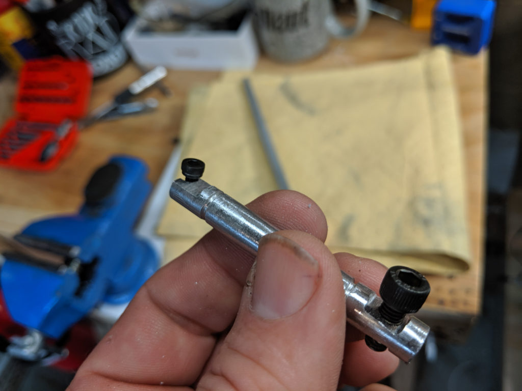
If all went well, and there is no reason for it not to, you will have a perfectly good threaded hole for which to bolt onto your coupler.

After all this was done I had to move on to the software aspect. The rover uses a raspberry pi running custom software (found here) that controls the servos and provides a local web interface from which to control Sawppy.
The Raspberry Pi is a small computer about the size of a deck of cards (give or take). It’s cheap and easy to configure with the OS being flashed onto an SD card. I have to admit it took me a while to properly get the software running right so that it would start with every boot and properly allow me to connect via my own local WiFi. I won’t bore you with that struggle as it would take many pages to explain. What matter’s is I finally got it working.
I was amazed actually at the range I was able to control the rover with my cell phone loading into the Raspberry Pi’s web server. The original plans called for utilizing a separate router set up as an access point to extend the range, but I was able to drive the rover up and down my block purely on the WiFi from my own house which lies directly in the middle of the entire block.
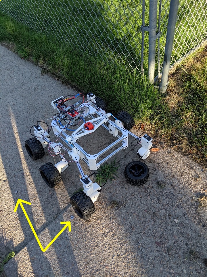 Here is a short video of her first test drive. Despite a wheel falling off immediately after I stopped recording all went well. The wheel was easily fixed and fell off because I didn’t tighten the nut well enough. I did notice that my choice of tires had some interesting consequences on its traversal across hard surfaces. Being as the tires were made of rubber, the angle of the upraised treads caused the wheels to want to bow outward as each subsequent rotation seemed to grip the pavement and caused the treads to ‘step out’ on themselves. All in all, I still considered it a great success.
Thanks for reading!

Chris Bond is the owner of this website, the father of three children, the husband of a wonderful woman, and the tinkerer of gadgets. He enjoys gaming, flying drones, building Gundam models, collecting robots and solving problems. He is currently a Senior Web Developer at NDIC.